Hi
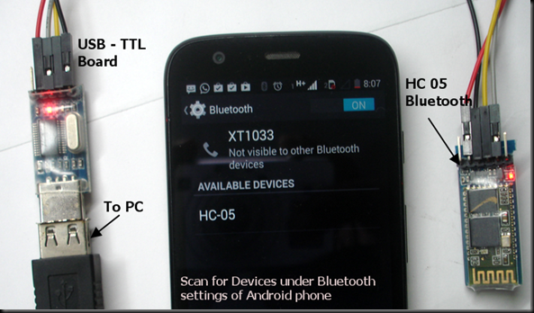
This article is about giving you an insight on how to interface your HC-05 to your Android powered handset using a bluetooth modem. generally this come without pin & it is very diffficult to connect them as show..
Basic diffierent between them is.....
This article is about giving you an insight on how to interface your HC-05 to your Android powered handset using a bluetooth modem. generally this come without pin & it is very diffficult to connect them as show..
Basic diffierent between them is.....
- The HC-05 module can build a connection to other modules. E.g. a Robot being a master and connecting to slave bluetooth module. Or in slave mode to make a wireless bridge to a notebook.
- The HC-06 module only can be a slave. This makes it only useful for say connecting a notebook as a master to a robot with a slave module e.g. for a wireless serial bridge.
To solve this we generally use JY-MCU as show ....to connect HC-05
- KEY: according to the data sheet, I need to pull-up this pin while power-on-reset of the module to enforce AT mode. I have not been able to verify this yet. I have been told that some modules have this pin not connected at all?
- VCC is indicated in the range of 3.6V-6V. The module worked for me both with 3.3V and 5V.
- GND: Ground
- TXD: serial output of the module, to be connected to RX of the microcontroller. Note that this signal is using 3.3V logic level
- RXD: serial input of the module, to be connected to the TX of the microcontroller. Note that this signal is using 3.3V logic levels.
- STATE: connected to LED2 (Pin32) of the module, but no meaning? At least on my module the pin was always low, regardless if paired or not.


